Pages

Monday 23 December 2013

Bufocam v2 Raspberry Pi PCB using Atmel 328 (arduino) microcontroller


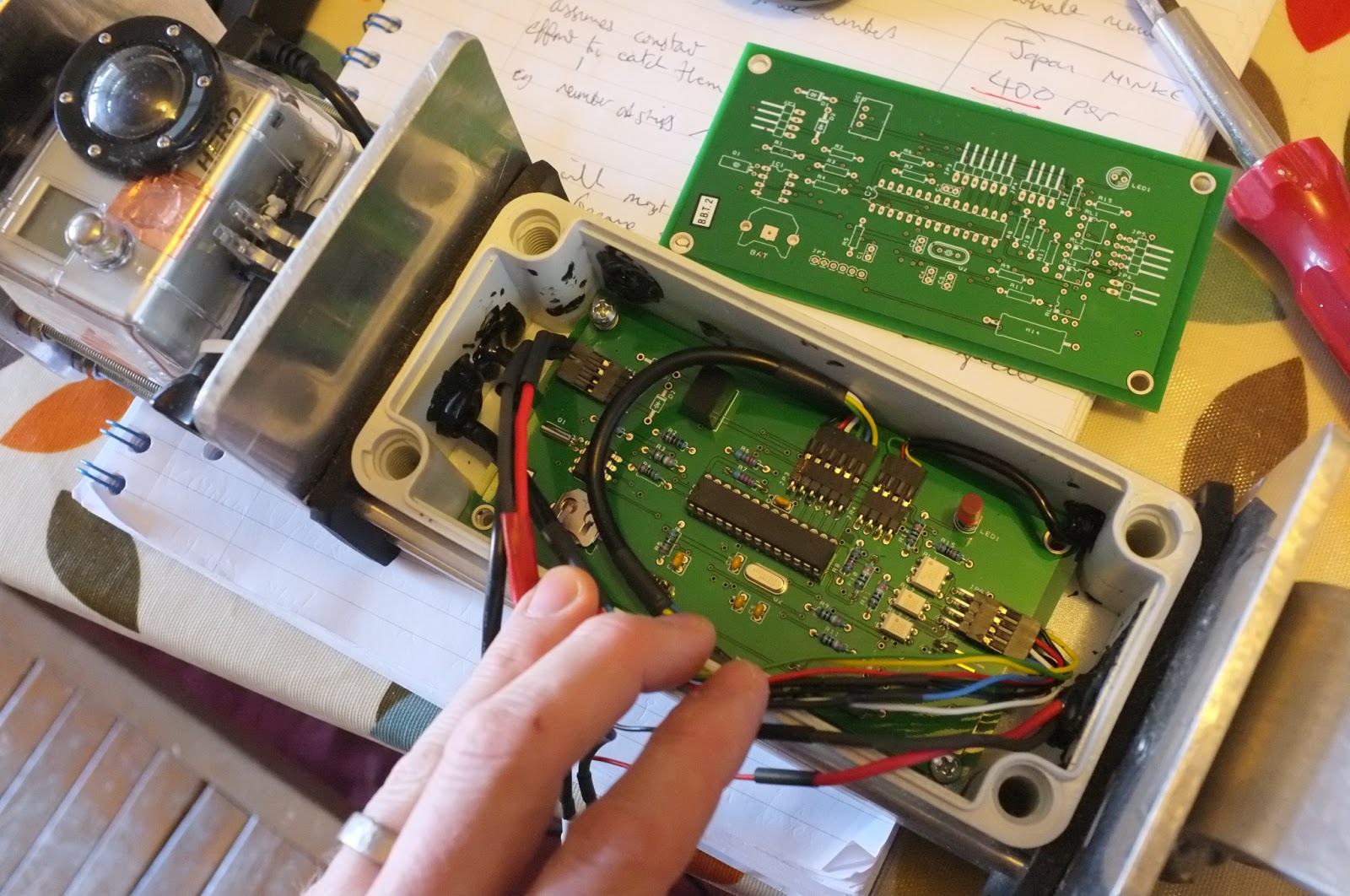
The breadboard/birds nest from the last post is now a shiny PCB - it just needs a box... and bit more programming. Three LEDs and a switch have been added but I haven't decided what they are for yet. Errors, probably.

To recap; the Arduino controls power to the Raspberry Pi via latched relay. Once the Rpi is up the Arduino just listens for commands on the I2C bus - such as measuring Vin, or controlling the pretty lights or killing the power.The Mosfet 'drivering' the IR LED array is directly controlled by the RPi GPIO. There's a real time clock on the I2C bus too. That's about it really.

Sunday 10 November 2013

Bufocam2: Raspberry Pi camera + M12 IR lens + Atmel 328 (arduino)

Figure 1. An ATMEL 328 (stripboard arduino with uno bootloader), latched relay, DS1307 RTC, camera, mosfet, some IR LEDS and a raspberry pi 'A'. The green and yellow wires are (mostly) an I2C bus on which the ATMEL328 and DS1307 appear as slaves.


Figure 2. one of 11000 images of a plastic toad and a fallen power droid under a cardboard box.


Tuesday 17 September 2013

tunnel data from april/may 2013


NB: there was no data for night 105 due to technical issues with the GoPro camera where it wouldn't take more than 4855 images. Recording effort was variable due to other sd card/firmware issues that arose on the second recording night, ( eg numbers on nights 113, 115 are probably representative.)

Friday 19 April 2013

Some toads!


Finally some results to be a bit proud of.
Despite a few technical problems, and thanks to the cold weather, we still caught the migration.
Here are some raw images;


Saturday 6 April 2013

SD card problems on GoPro? - corrupt jpeg frames.

Testing prior to installation in the next tunnel, and I'm getting a few images that look like this;


GIMP is saying Unexpected end of JPEG file...

Anecdotal evidence on the internets suggest it's the sd card, so i'll try changing that first.

UPDATE
Using a Samsung Pro 32GB card like this one seemed to mitigate the problem for one night, then the corruptions begin again. We are also losing files - the whole image is black and only about 127kb;

http://www.maplin.co.uk/samsung-pro-32gb-sdhc-memory-card-719982
(I wouldn't actually recommend you buy it from Maplin)


I don't know if it really is the SD card.

UPDATE 2
This seems to have been cured by the last GoPro firmware update. It wasn't the SD card.

Finished circuit board


Wednesday 13 March 2013

BufoCam ATMEL circuit board - Bufoduino?

Convention dictates I call this 'bufoduino'. You can, if you like. I'm still calling it BufoCam.

Much credit is due to the resources at adafruit, which saved me looking at the DS1307 datasheet. (I'm planning to plug their sd-breakout into the SD Card socket so I can seal the control hardware away and have the SD card accessible to the user.)


Thursday 21 February 2013

GoPro IR conversion - stock optics lens

Converting a GoPro HD2 is a lens swap. I believe the IR blocking filter unscrews from the back of the original GoPro - but it isn't the case with the GoPro 2 as the filter is coated on the back of a convex-Plano element.

We tried to order a GoPro 1 lens from ragecam in the states, but it got stuck in customs for so long I had to find an alternative. It was stuck primarily because nobody told us it was there.

Anyway, in the meantime I found a cheaper solution;


http://www.stockoptics.com/board-lenses/cctv-board-lens-day-night-megapixel.html
CCTV-BL-D/N-2.5-5MP-400-950nm

Field of view is smaller, so we might swap it out for the ragecam lens at some point... 

If you are thinking of changing a gopro lens there are lots of videos to give you an idea of what's in there on you tube - but I found taking the camera apart was quite straightforward. Most of the instructions I've seen use a heat gun to free the lens. If, like me, you bought the cheaper heat gun you could fin in cpc/poundland then you could try a dab of pure acetone on the lens thread.

Bufocam prototype and cradle installation


Sunday 17 February 2013

Gopro IR timelapse with arduino shutter control

Previous attempts to reduce the timing window of the 900mW IR LED led to an unstable system, suggesting the time of the GoPro to power up and take the first image (2800 by experimentation) was shifting over time.

In order to reduce the power requirement of the IR lamp, and eliminate the sporadic timing of the GoPro one-button timelapse image, the shutter button of the GoPro has been hard wired to a third solid state relay. Grounding the wire via the relay for 250ms appears to work well, but attempts to reduce the timing window below 750ms have so far failed. This is still frustrating, but a great improvement. If the light comes on too late the image is burnt out, but if it turns off too early it produces a black frame. Presumably the GoPro is taking half a second or so to process a meter reading?

There was some improvement though and another 24hr trial was needed to assess how much difference this had made..


Battery Results


The gradient of the Vin results above look a bit better than in previous experiments.
 However, it would appear there are still stability issues.
According to the shutter count on the data log 2902 images were expected, but only 2873 were found.

Size on disk 6.92 GB (7,439,613,952 bytes)
contains 2,873 Files, 3 Folders


On further scrutiny there are 10 bad images (full frame black) in the first folder, GOPRO100 and 7 bad images in GOPRO101. Timing of the images appears sporadic throughout the test time.  Otherwise the first 2771 images look ok, but 16hrs 54mins into the test in GOPRO102 an image appears under the timelapse naming convention, another appears after a few minutes, and then a number of timelapse images at approx 17hr 29mins. Other than being incorrectly named  (eg G0010703 instead of GOPR0703.) these images are OK. None of the timelapse images have sequential numbering, so they aren't really a conventional timelapse sequence.

After 17hrs and 36mins lots of bad images begin to occur. There is the occasional good image, and the occasional bad name, just to confuse things, but the results are really unstable.

Looking at the battery voltage graph for the lithium battery during this period of instability it appears that the battery is under load at about 3.7V which would suggest the camera has failed to turn off for some reason...


Present timings


  digitalWrite(cameraPower, HIGH);
  delay(250);                   
  digitalWrite(cameraPower, LOW);
  delay(3000);
  digitalWrite(cameraShutter, HIGH);
  delay(250);
  digitalWrite(cameraShutter, LOW);
  digitalWrite(irLEDpin, HIGH);
  delay(750);
  digitalWrite(irLEDpin, LOW);
  delay(100);
  digitalWrite(cameraPower, HIGH);
  delay(3000);
  digitalWrite(cameraPower, LOW);
  delay(250);
  digitalWrite(cameraCharger, HIGH);
  delay(10000);
  digitalWrite(cameraCharger, LOW);


Tulips


Monday 11 February 2013

More Arduino / GoPro battery woes


The flat line


Notably there are no flat lines in the NiMH battery curve. During the daylight interval, where no images are being taken, it would be desirable to use as little current as possible. There are a few issues here;

The UNO board is powering serial - USB hardware and some LEDs. 
SD card is possibly taking current when not datalogging.
Sleep modes have not been effective, they seem to break the datalogging and don't turn off the extra hardware.

Action here requires a stripped down processor board. (like this one http://www.gammon.com.au/forum/?id=11109 ). It would seem sensible to put the rest of the hardware on that board too and do away with plugs and shields. Lowering the clock speed of the Atmel328 may also be prudent.

Sleep modes may require closing the file and reopening/reinitializing the sd card instead of flushing the file. Further work is needed here. Other tricks to save power involve changing he data pins to inputs and using a mosfet to lift the ground of the SD card.

The yellow line

At some point around 20hour the GoPro timing shifts out of the lighting window. Other tests have also exhibited half frames, but the results are using black frames of around 260kb. Extending the lighting window to 3 seconds will rectify this, but this is seriously detrimental o battery life.

Presently the system is momentarily pulling pin 12 of the GoPro connector low and the light comes on 2500ms later. Theoretically the timing of the first frame should be a known quantity but while experimental results appear to show this occurs at 2800ms this has not produced reliable results in the camera. (characteristic black and half black frames as the 'shutter' timing slips out of the lighting window.

Fixing this is going to require a hardware hack, two wires to close the shutter button remotely through another relay or an optoisolator.


Charging the GoPro


A two battery system has to present some loss of efficiency. At present anecdotal evidence suggests the camera will forget the date and time if the battery is removed for any length of time. It is imperative that the images retain correct date and time of creation.


Temporary solution


Replace the NiMH with a high capacity lithium battery!


Power saving and the RTC


good thread here

http://www.gammon.com.au/forum/?id=11149

Dump the power on the RTC when it isn't it use.


Sunday 3 February 2013

More Battery Life


Based on the last test the GoPro isn't going to last the night (at least not in winter) without some help. This test uses a charge interval after each image capture . The example data here run for ten hours (before I couldn't resist having a look) previous tests have run for twelve hours. (There's currently a test running under the stairs that started last night at 10pm which I'll have a look at in the morning.)

A ten hour test using a two second lighting interval and charging the GoPro for five seconds between each capture. The exact GoPro start up time and initial capture timing is unknown. If these can be measured the lighting duration could be reduced. If there isn't enough light the system behaves erratically, the camera can produce black or corrupt files and the system can get out of sequence. Subsequently it has been hard to deduce the timing window from trail and error and it has been safer to leave the duration at two seconds than risk jeopardizing the experiment. If the demands of the lighting subsystem on the overall battery status are insignificant compared to the charge duration it might not be worth the time it would take to investigate this properly.


The charge in the GoPro camera is slowly creeping down so I'm running the current test with a slightly longer charge interval.

The debug LEDs can be turned off, and the board is still taking 40mA idle which could be improved on. Ultimately these factors may also be insignificant, but it might be prudent to look at sleep intervals - particularly during the day. (The data logging interval period and SD card flush frequency are going to be longer in the 'real thing too, which may make some really small difference.)

These result look hopeful. Even if the NiMH battery doesn't perform so well in the cold, a lithium ion battery or lithium polymer would offer a better charge density albeit at a greater cost.


Friday 25 January 2013

Battery life

the dip at the end of the red line is the GoPro battery giving out. Nearly 8 hours at one frame every twenty seconds - it needs to be better than that, so the camera battery is going to need to be topped up between shots.

The voltage drop on the big battery looks concerning... maybe I forgot to charge it?

To help the arduino it may be powered from the switch mode regulator on the power board via the USB.

Could try putting it to sleep for a few seconds, this may upset the timer. (use the RTC for image/logging times?)

The debug LED's will be taking a little bit a current too.

Before fucking about it might be prudent to get an meter across the NiMH current output...


...looks like approx 60mA running - up to about 85 mA whilst firing the shutter. (including the dummy green LED, which will be a much bigger IR LED on the day.)

Five minutes later and, after hacking a USB B connector off and blobbing onto the back of the switching regulator we are looking at about 36 mA 'standing around' charge.

Thursday 24 January 2013

timelapse fun with arduino and gopro

I do all my best work with a baby strapped to my front (it's the only way she will sleep more than 30 minutes).

This seems to work anyway... just as they said it would. I'm using these pins;

1 GND
5 +5v input
6 +5v input
12 PWR button
23 battery voltage
24 battery voltage when powered, otherwise 0v
30 GND

Grounding 12 to take a photo,  monitoring the gopro battery on 23 and charging it on 5,6.

The GoPro is setup for a 10 sec timelapse in one button mode. It takes a picture when it powers up - then is powered down. The timing is off for the IR LED at present - the green LED in the photo should be on!

There are a few sites out there with instructions on building this - I've already posted links to most of them, thanks to everyone who put the time in to reverse engineer the HD bus connector, and make that information public... not to mention risk their camera grounding misc pins.

I've grounded my pin 12 with a solid state relay and i've added is a mosfet to drive my IR LED lamps. The voltage on pin23 is being logged on the SD logger shield with my temp/RH data, timestamp, and the shutter count.


Creative Commons License
This work is licensed under a Creative Commons Attribution-NonCommercial 3.0 Unported License